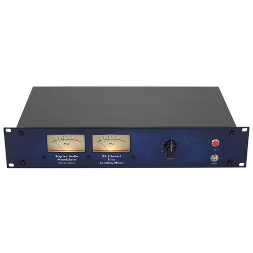
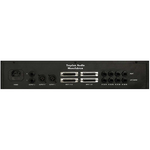
Complete True Large-Format Analog Summing Bus with Stereo Insert
Essential Studio Control Room Monitor Features
Artist Cue/Talkback
High Power Headphone Amp
Classic Electrodyne 1970's Large-Format Console Summing and Stereo Mix bus:
- 16 channel active summing network and stereo bus with fully balanced stereo insert path.
- Transformer balanced analog outputs. Transformer control for "tight" vs. "warm" mix bus sonics.
- Precision Detented Master Bus Level Pot with Stereo Bus Calibration Trimmers.
- Original Electrodyne design transformers and discrete transistor op-amps throughout.
Studio Quality Control Room Monitor Section:
- Stereo Mix, Artist Cue, XLR and 1/8" Mobile Device Inputs.
- Precision Detented Control Room Level Pot.
- Mono, Dim and Mute Controls.
- Main/Alt Monitor Selector with Precision Level Trimmers for Alternate Speakers.
- Extremely Low Distortion Balanced Signal Path for Quality and Accuracy of Monitoring.
- High Power, Low Distortion Headphone Amplifier.
Artist Cue and Talkback:
- Cue Input Talkback Loop for Artist Headphone / Studio Monitor Mix.
- Integrated Talkback Microphone with Control Room Monitor Dim function and Remote Talkback Jack.
- "Control Room Listen" Function Allows Artists in Studio to Hear Control Room Sources (Playback,
Rehearsal, etc.)
ELECTRODYNE AUDIO - Summing Station
Controls and Connectors
FRONT PANEL:
SUMMING SECTION:
1) MONO 1-2, MONO 3-4 buttons: Changes stereo pairs 1-2 and 3-4 to two mono channels each. This allows two or four mono sources
(eq: Kick, Snare, Lead Vocal, Bass, etc…) Avoids using up a stereo pair for mono tracks.
2) MIX level knob: 31-step detented Master Stereo bus level for accurate recall. “0” setting is unity gain. +6db of gain above unity is available for boosting mix levels.
3) INSERT button: Engages a fully balanced Stereo bus insert for mix mastering and stereo processing gear.
4) BUS trimpots: Allows trimming +1.5db/-3db for exact stereo bus levels to your stereo master recorder (DAW, Stereo tape machine, etc...)
5.) -TRANSFORMER button:Changes mix bus tones by switching mix amps and output transformers to two different configurations.
“WARM”, classic 1970’s full transformer harmonics.
“TIGHT”, smooth and silky with controlled harmonics.
CUE / TALKBACK SECTION:
6) TALKBACK button: Mutes incoming CUE or CR LISTEN audio and sends Talkback Mic to CUE bus outputs.
7) TALKBACK level knob: Adjusts level of Talkback microphone to CUE bus outputs.
8) Talkback Mic.
9) CR LISTEN button: Switches CUE output from CUE input, to audio selected on CONTROL ROOM source selector buttons.
10) CR LISTEN level knob: Adjusts level of audio from CONTROL ROOM source selector to CUE outputs, when CR LISTEN is engaged.
CONTROL ROOM SECTION:
11) EXT-1 button: Selects Control Room input from 1/8” front panel jack. For SmartPhone, MP3 player and other portable audio devices.
12) EXT-1 front 1/8" jack: For personal/mobile electronics (Smartphone, MP3 player, etc..) Standard 1/8” stereo audio input jack, over-rides rear 1/4”
TRS jack when plugged in. (-6db nominal level)
13) EXT-2 button: Selects Control Room input from rear panel balanced XLR connectors.
14) CUE button: Selects Control Room input from CUE input xlr's.
15) MIX button: Selects Control Room input from Summing section Stereo mix bus.
16) CONTROL ROOM knob: Controls level of studio monitor speakers.
17) MONO button: Folds stereo signal to mono (for phase checking, mono compatibility, etc..)
18) DIM button: Reduces CONTROL ROOM level by approximately 20db.
19) MUTE button: Mutes studio monitors.
20) MONITORS button: Selects MAIN or ALT monitor speaker sets.
21) ALT trimpots: Adjusts level of ALT speakers for matching MAIN speaker levels.
Factory default setting is no attenuation (equal to MAIN). Adjustments should be made by setting level controls on your ALT speakers louder than
Main, and turning down ALT trimpots to match MAIN speaker levels.
22) HEADPHONE level knob: Adjusts level of HEADPHONE amplifier. (NOTE: Headphone amp can be set Pre or Post Control Room level. (see internal
jumper settings).
23) HEADPHONE jack: 1/4” TRS jack for professional headphones.
WARNING !!! HEADPHONE AMP HAS SIMILAR POWER TO PROFESSIONAL STUDIO CUE SYSTEMS AND CAN GENERATE EXTREMELY HIGH LEVELS !
PLEASE PROTECT YOUR HEARING.
REAR PANEL:
24.) -AC INLET: AC 110 or 240vac. selectable.
25) OPTIONS (purchased separately): AES D/A converter input, AES A/D converter output, WORDCLOCK input. (Release dates: TBA.)
26) EXT-1 rear jack: 1/4” Stereo TRS audio input (see pinouts page). (-6db nominal level)
27) TALKBACK REMOTE jack: Remote connector for external Talkback switch. Use momentary contact switch connected to TIP and RING only. SLEEVE
(shield) Not connected, (see pinouts page).
28) MIX OUTPUT (left/right): Summing Section stereo bus outputs. Transformer balanced XLR Male connectors. (+4db nominal level)
29) EXT-2 INPUT (left/right): External-2 inputs to Control Room source selector button. Active Balanced XLR Female connectors. (+4db nominal level)
30) 1-8 input: DAW input connection. (+4db nominal level) db-25 Tascam standard Analog Input wiring, (see pinouts page).
31) 9-16 input: DAW input connection. (+4db nominal level) db-25 Tascam standard Analog Inputwiring, (see pinouts page).
32) MIX INSERT / CUE I/O: db-25 Summing Section stereo bus INSERT input/output and CUE section input / outputs. db-25 Tascam standard AES I/O
wiring,(see pinouts page). (+4db nominal level)
33) MONITORS / METER / MIX MULT: db-25 MAIN and ALT Studio monitor speaker outputs, Stereo METER buffer amp outputs, Stereo MIX bus outputs. db-25 Tascam standard Analog Output wiring, (see pinouts page). Output levels optimized for active (self-powered) speaker systems.
SYSTEM PERFORMANCE NOTES:
1.) Output levels listed at positive “Full Scale” values (eg: +6fs) are shown only to illustrate Summing Station extended headroom, and capability of
exceeding input levels of standard digital converters, not for typical operating levels.
Operating the Summing Station within normal studio levels will provide superior performance and sound.
2.) Refer to pinouts page for input / output connector types, connector pinouts and accessory wiring notes.
3.) Summing Section thd/frequency response graph shows separate response curves for swept sine wave, with “TRANSFORMER” in WARM and TIGHT
settings.
Summing Section harmonic response will vary depending on average levels, dynamic range, frequency balance and harmonic content of original
material, and “TRANSFORMER” setting on SUM section.
4.) Low frequency rise in Summing Section graph shows accumulation of flat response level from test signals plus natural harmonic contributions from
Summing Station discrete transistor summing opamps, mix bus opamps and output transformers.


